|
|
|
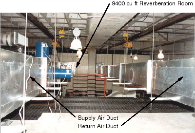
The test facility at CMEST
for the airflow performance and sound testing of duct elements has two
fan rooms that are adjacent to each other. The fan rooms are on a
mezzine level approximately 90 ft from the front of the 9400 cu ft
reverberation room. One room contains the supply air fan and the other
contains the return air fan. The fans can be operated independently or
in parallel. Air can be drawn in from the outside and discharged to the
outside. For this configuration the dampers between the two fan rooms
are closed and the inlet and discharge air dampers to the outside are
open. Air can also be directed in a closed loop between the
reverberation room and the two fan rooms. For this configuration the
inlet and discharge air dampers to the outside are closed and the
dampers between the two fan rooms are open. Between the fans and the
ducts that connect the fan rooms to the reverberation room are a sound
plenum, a ten-foot silencer bank, and another sound plenum. The length
of the ducts between the second sound plenum and the reverberation room
is 90 feet. The maximum size of the ducts that can be placed between the
fan rooms and the reverberation room is 5 ft by 5 ft or 5 ft diameter.
The picture below is a picture of the supply and return air ducts that
are placed between the fan rooms and the reverberation room. The duct on
the left is the supply air duct and the duct on the right is the return
air duct.
The fans in the two fan rooms are six-foot diameter
Joy vane axial fans. Figure 8 shows the inlet section of the return air
fan. The fans are variable-speed, adjustable-pitch fans. Each fan is
controlled by a 65 horsepower, variable-frequency inverter. The pitch of
the fan blades of each fan can be adjusted after the fan has come to a
complete stop. Using the adjustable pitch capability of each fan along
with its variable-frequency inverter, the flow capacity of each fan can
be varied from 1,000 cfm to around 60,000 cfm at a total static pressure
of 4 inches H20. As was mentioned above, the fans can be
operated individually, or they can be operated together with each fan
running at the same rpm.
A rail with a movable one-ton hoist is located above
the entire length of each duct between the fan rooms and the large
reverberation room. The ducts are usually installed in ten-foot
sections. Thus, it is possible to change out complete or partial duct
runs with a reasonable amount of effort.
The current configuration of ducts is set up to
conduct ASTM E477 tests on duct silencers. The sections of duct between
the fan room and the test section are constructed of dual-wall ducts
with a cavity depth of 4.25 inches. The inside dimensions of the ducts
are 24 in by 24 in. The inside and outside walls of the ducts are
constructed of 18 gauge sheet metal and the cavity is filled with
fiberglass. The sections of duct between the test section and the
reverberation room are constructed of dual-wall ducts with a cavity
depth of 2.25 inches. The inside and outside walls of the ducts are
constructed of 18 gauge sheet metal and the cavity is filled with
fiberglass. Silencers with lengths of up to 10 ft can be tested. There
are test sections in both the supply air and the return air ducts.
The sound source for the ASTM E477 test consist of
three speaker canisters that are mounted directly to the duct walls of
either the supply or return air duct. One canister contains a 500 watt
18-inch diameter low-frequency speaker; the second canister contains a
500 watt 8-inch diameter mid-range speaker; and the third canister
contains two 50 watt high-frequency tweeters. The power source consists
of a single-channel equalizer, a three- to five-way adjustable crossover
network, a 1,000 watt stereo amplifier (500 watts per channel), and a
100 watt monaural amplifier. Pink noise is directed into the equalizer.
The crossover network is adjusted with crossovers at 300 Hz and 3,000
Hz. Sound energy at frequencies less than 300 Hz is directed through one
channel of the stereo amplifier to the low frequency speaker. Sound
energy at frequencies between 300 Hz and 3,000 Hz is directed through
the other channel of the stereo amplifier to the mid-range speaker.
Sound energy above 3,000 Hz is directed through the monaural amplifier
to the high-frequency tweeters.
Two piezometric rings, one placed ten feet upstream of the test
section and the other placed ten feet downstream of the test section,
are used to measure the static pressure drop across a duct silencer or
other duct element that is being tested. A Pitot tube rake (five
individual Pitot tubes connected to a single manifold), along with the
upstream piezometric ring, is used to measure the velocity pressure and,
consequently, the flow velocity and flow volume of the air flowing in
the duct during a test. The static pressure drop and the velocity
pressure are continuously monitored by means of differential pressure
transducers that are connected to digital meters. Piezometric rings and
Pitot tube rakes are located in both the supply air and the return air
ducts.
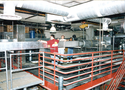
Students setting up for airflow
friction loss tests of a
rectangular duct that is internally lined with fiberglass. |
|
|